


Dapeng Town Industrial Park, Tongshan District, Xuzhou City, Jiangsu Province, China
The space frame structure is divided into: cross truss system, quadrangular pyramid system and triangular pyramid system according to different space frame forms.
The space frame structure of the single-storey automobile industrial plant generally adopts the quadrangular pyramid space frame that is placed orthogonally. This kind of structure is simple in shape and convenient to manufacture, especially in the case of a suspended crane, a positive-placed quadrangular pyramid space frame with greater spatial rigidity is more advantageous.
The node connection method between the space frame frame and the column is divided into: upper chord support type and bottom chord support type.
The upper chord support is beneficial to the stability of the space frame itself in the plane, but it is not conducive to the stability of the column. In the automobile industry workshop, the space frame structure with large span and large column spacing is generally used due to the process requirements, and the bottom chord support is generally used.
The selection principle of the space frame support is: the mechanical mode of the space frame design support must be consistent with the designed support structure.
The space frame supports are divided into pressure support nodes and tension support nodes. The pressure bearing nodes mainly include: flat plate pressure, single-sided arc pressure, double-sided arc pressure, and spherical hinge pressure bearing nodes. Tension bearing nodes mainly include: flat plate tension, rubber plate type, and single-sided arc tension bearing nodes. In the automobile industry workshop, flat supports and single-sided arc supports are used more.
There are two types of space frame ball joints: welded hollow balls and bolted balls. The welded hollow ball joint has a simple structure and clear force transmission, but the on-site welding workload is large, the welding quality requirements are high, and the welding deformation is easy to cause dimensional deviation. The bolt ball joint avoids a lot of on-site welding workload, and the specifications of spare parts are easy to serialize and standardize, which is suitable for industrial production. However, the bolt ball joint also has problems such as complex joint structure, large amount of machining, and high production cost. It is generally suitable for small and medium-span space frame, and the length of the rods should not exceed 3m.
The calculated length of the space frame member is determined according to the form of the spherical node. When the bolt ball is used, the calculated length of the chord, the web of the support and the web is 1.0L; when the welded hollow ball is used, the calculated length of the web of the chord and the support is 0.9L, and the calculated length of the web is 0.8L . (L is the geometric length of the rod).
The allowable slenderness ratio of the tie rods in the space frame members: 250 for the rods directly bearing the dynamic load and the rods near the support, and 300 for the general rods; the allowable slenderness ratio of the compression rods is 180. Because the process load of the lower chord of the space frame structure is uniformly distributed, the most unfavorable layout should be considered. In addition to the full load, the load should also be arranged in a checkerboard pattern.
The height-span ratio of the space frame can be 1/10-1/18, usually within the range of 2-6 m; the length and width of the space frame should be equal or not. The number of space frames in the short span of the space frame should not be less than 5. The length of the space frame members is generally controlled at 3 to 6 m, and the angle between the web and the ground should be controlled at 30 to 60 degrees, preferably 45 degrees. The internal force of the web is generally only 1/3 of the internal force of the upper and lower chords 1/6[4]. In order to improve the stiffness of the space frame, the deflection control value of the space frame is increased to 1/300 to meet the requirements for the stiffness of the space frame by the process hanging.
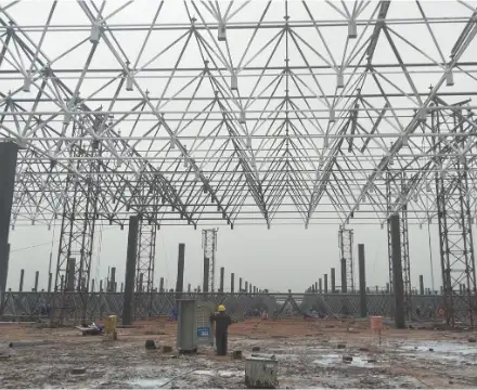
The total length of the welding workshop of a factory building is 248m, the width is 54m, and the main column space frame is 27mx24m. The process load distribution in the factory building is uniform and large (mainly 3KN/m2). The roof design of this factory should adopt a space space frame structure. According to the temperature division, the welding workshop is divided into 120m and 127m in the length direction, taking 120mx54m as an example. When designing the space frame column, it is safe to take μ=2. Plant load settings: roof dead load 0.3KN/m2, roof live load 1.0 KN/m2, process hanging loads are 2.8KN/m2, 3.0KN/m2.
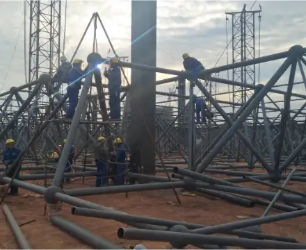
The welding workshop adopts the square-cone type, the main column space frame is 27mX24m, the lowest point height of the space frame is 2.4m, and the slope is 5%. The size of the space frame is 3mx4m, and the bottom chord is supported. The space frame ball joints have welded hollow balls and bolt balls, the calculated length of the rods is taken as 1.0L, and the slenderness ratio of the tie rod and the pressure rod is taken as λ=180. The space frame structure adjusts the arrangement of the outer ball nodes of the upper chord of the space frame frame, so that the outer ball nodes of the upper and lower chords are aligned, which is convenient for the installation of wind-resistant short columns on site, and there is no need to use auxiliary beams to connect the wind-resistant short columns. However, this method affects the setting of the small column of the pipe support. One side of the peripheral axis pipe support needs to be connected to the vertical web rod, and the vertical web rod needs to check the pipe load. If it is insufficient, the section size of the rod needs to be increased to ensure that the strength requirements are met.
Considering the effect of wind load, single-sided arc pressure bearing nodes are used for the outer column top supports of the welding workshop. The arc-shaped plate of the support is in line contact with the bottom plate on the support, which can make the support have a small amount of rotation and a small amount of linear displacement. The center column support adopts the flat plate pressure support node, which is simple in structure, convenient in processing and saves in steel consumption.
space frame calculation: The space frame adopts the 3D3S V12.1.1 space frame module developed by Tongji University for modeling and calculation optimization, and the post-processing module is used to draw construction drawings.
The total area of the welding workshop is 13392 square meters, which is equivalent to 36.3 kg/㎡ of steel consumption per unit.
space frame structure design is not only the application of software, but also a clear understanding of the concept of space frame structure design. In the design of the space frame, the most important point is to choose the structural form that conforms to the actual situation and comprehensive conditions of the project, which is mainly reflected in the selection of structural form, support form, bearing form, and ball joint form. The ultimate guarantee of structural safety, economy and construction convenience.


