


Dapeng Town Industrial Park, Tongshan District, Xuzhou City, Jiangsu Province, China
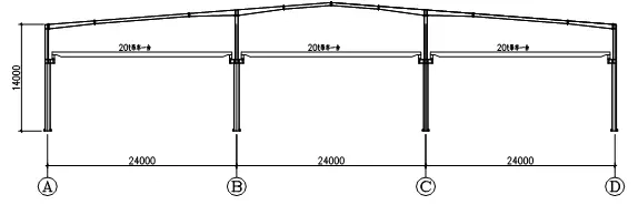
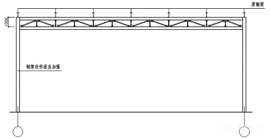
The original plant location seismic intensity of 6 degrees, the first group, site category II. Plant structure for 3 equal span (24mx3), column distance of 6m, eave height of 14m, double slope, each span has a lifting capacity of 20t bridge crane, detailed Figure 1. due to changes in the use of plant function, the original span of 24m can not meet the requirements of use, requirements for 2 equal span, each span of 36m, that is, the removal of B, C axis steel column, and in the middle of an additional steel column. At the same time, the use of bridge cranes was cancelled.
Steel columns and beams are all made of welded H-beams. The design service life of steel frame structure is 50 years, safety grade II, structural importance factor is 1.0. basic wind pressure is 0.35kN/m2, ground roughness category is B; basic snow pressure is 0.45kN/m2, roof constant load is 0.2kN/m2, roof live load is taken as 0.3kN/m2 when calculating steel frame. internal use function changes, roof constant live load takes the same value.
1. Reinforced steel beam program
Using PKPM software, after the original 24m span is changed to 36m span, the strength of steel beam can’t meet the load requirements, and the strength of side span columns of A and D axes meet the requirements because the crane load is cancelled. Therefore, reinforcing the steel beam is the most direct and effective solution. As shown in Figure 2, the effect after reinforcement is shown.
Using PKPM to calculate the single-bay steel frame, the maximum cross-sectional height of the 36m-span steel beam should be 1200, and it is necessary to add welded T-shaped steel plates to the lower part of the original design H-beam to meet the strength requirements, in addition to the structural requirements such as the height-thickness ratio and width-thickness ratio of H-beam. Figure 3 shows the cross-sectional approach of the reinforced steel beam.
The advantages of this transformation program are: the net height of the original use after reinforcement will not be reduced too much, the model force is clear, the calculation is simple, and the transformation cost is low. The disadvantage is: the original H-beam web needs to be thickened by welding steel plates to meet the strength requirements, and the construction is difficult and inconvenient in the case of beam height change.
2. Additional truss solution
Add 1/B axis center column, cancel B axis and C axis steel frame column while attaching steel cross beam and chord to form truss system, the original steel beam as truss upper chord is not modified. As shown in Figure 4.
The advantages of this modification scheme are: the joist has strong bearing capacity, especially for the case of special hanging load requirement in the lower chord of the joist, it has obvious advantages. The disadvantage is: it will occupy more space, the net height may not meet the requirements, and the construction is more inconvenient.
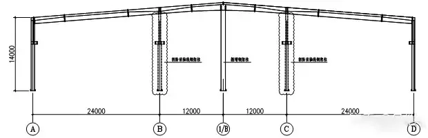
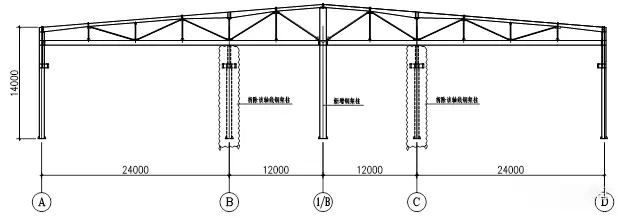
3. Longitudinal additional bracket program
In the lower part of the B-axis and C-axis steel beams where the steel frame columns are to be eliminated, brackets are set along the longitudinal direction to hold up the steel beams, and a steel frame column is kept as the support column of the brackets at intervals, and the column is properly strengthened. The strength meets the requirements after calculation by PKPM software. The form of the bracket is shown in Figure 5, and the arrangement of the bracket in the plane is shown in Figure 6.
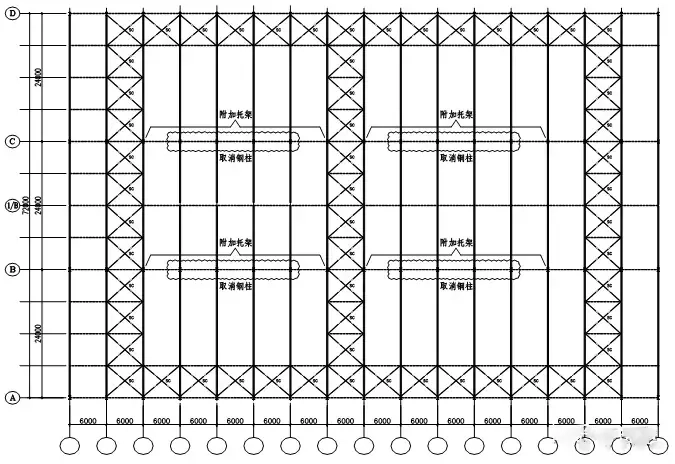
The advantages of this transformation program are: the brackets can be installed after the ground is processed, the construction is more convenient, and the transformation cost is smaller. The disadvantages are: the steel frame columns of B-axis and C-axis are not completely cancelled, but will be kept in part, and the setting of the brackets should be considered in conjunction with the actual functional arrangement of the plant; in addition, the large span of the brackets will lead to large deflection in the span, and it is crucial to ensure the common action of the steel frame beams of each bay after the deflection of the brackets occurs.
Each of the above three options has its own applicability and needs to be considered according to the actual situation of the project and the owner’s requirements in terms of construction period and cost.
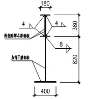
1.due to the original design with crane beam, and set the bull leg, the side column of the upper and lower column cross-section is not consistent, on the one hand to consider the aesthetic factors, on the one hand to ensure that the upper column in-plane stiffness to meet the requirements, the upper column will be added welding T-shaped steel, so that it is consistent with the lower column cross-section. As illustrated in Figure 7.
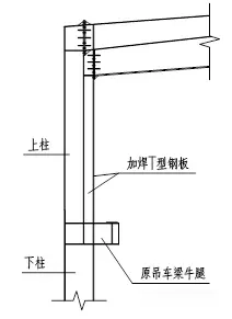
2.Since the original design of the crane beam plays the role of a bollard, so if the crane beam at the side column position is to be cancelled after the transformation, a bollard needs to be added at the corresponding position to ensure the out-of-plane stability of the side column.
1.during construction must be first top before demolition, that is, first to do a good job of temporary support, before the removal of steel columns;
2.in the good reinforcement measures unloading process, must pay attention to monitor the deformation of steel columns, steel beams.
The construction drawings of this project finally chose option three, mainly for the sake of the construction period, without the need for additional foundation construction links, and the later use of good conditions. Through the comparison of the three options, to provide a kind of portal steel frame plant transformation ideas, the utilization rate of the warehouse is not high after the transformation of reuse, played a positive role.


